
How to Choose the Suitable Agitator for Your Jacketed Stainless Steel Reactors
2026-07-31
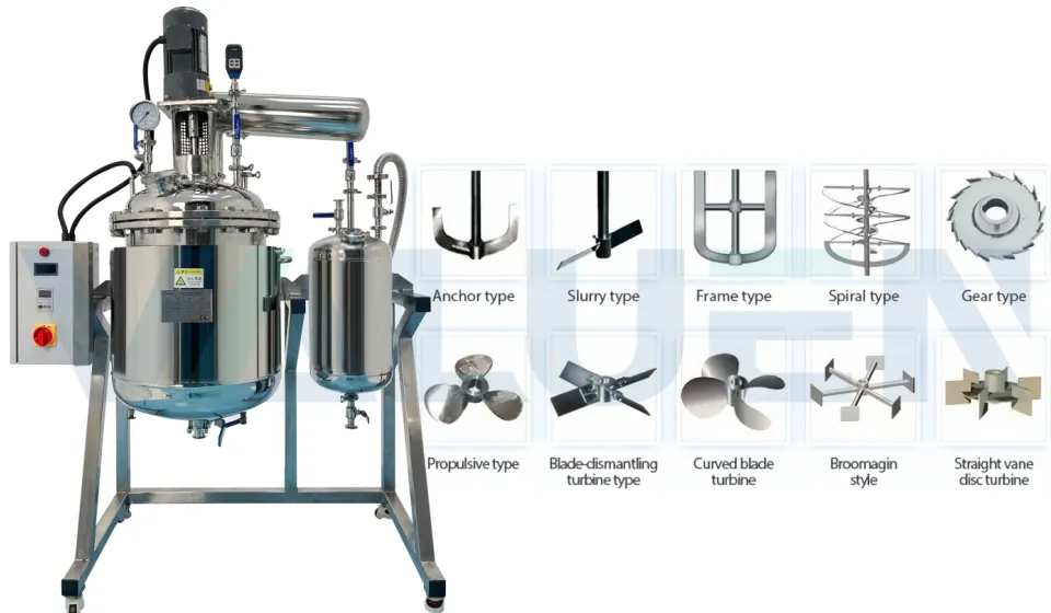
How to Choose the Suitable Agitator for Your Jacketed Stainless Steel Reactors
Selecting the appropriate agitator for your stainless steel jacketed reactor ranks among the most consequential decisions in process design. The agitator serves as the driving force behind mixing—it governs reaction efficiency, final product quality, and overall energy consumption. An ill chosen agitator can create stagnant zones, uneven temperature distribution, and product inconsistencies, ultimately leading to batch failures. Conversely, a properly matched unit ensures optimal mass transfer, uniform heat exchange, and a smooth scale up pathway from laboratory trials to full scale production.
This guide provides a structured methodology for agitator selection, matching impeller geometries to specific process goals and fluid characteristics.
The Three Core Factors in Agitator Selection
Before examining impeller types, you must evaluate three fundamental aspects of your application: the process objective, the physical properties of the fluid, and the required flow behaviour.
1. Identify Your Process Objective
What do you intend the agitator to achieve? Different goals demand distinct fluid-motion patterns:
Liquid Liquid Blending: Achieving a homogeneous mixture of miscible liquids calls for bulk circulation and efficient axial movement.
Solid Suspension: Keeping particles evenly dispersed requires strong vertical currents to counteract settling.
Gas Dispersion: Breaking gas streams into fine bubbles for reactions like hydrogenation demands high local shear.
Heat Transfer Enhancement: Moving fluid across the jacket or internal coils requires flow patterns that effectively sweep the vessel wall.
Emulsification: Producing stable emulsions with controlled droplet size depends on precisely applied shear.
Each objective naturally points to a different impeller geometry.
2. Characterise Your Fluid
Fluid properties—especially viscosity—are the most decisive factor in impeller selection.
Low to Medium Viscosity (up to ~50,000 cP): Fluids in this range behave like water or light oils. Standard turbine or hydrofoil impellers operate effectively in the turbulent regime. Baffles are essential to prevent vortex formation and ensure thorough mixing.
High Viscosity (>500,000 cP): Pastes, polymers, and heavy slurries behave quite differently. Conventional open impellers simply carve a channel through the material without moving the bulk fluid. These applications require close clearance designs—such as anchors or helical ribbons—that physically sweep the vessel wall and operate in the laminar regime.
Non Newtonian Fluids: For materials whose viscosity changes with shear rate, selection becomes more involved. Rheological behaviour must be carefully analysed, often favouring close clearance designs to maintain uniform motion throughout the entire volume.
3. Understand the Flow Pattern
Impellers generate one of two primary flow modes:
Axial Flow: Fluid is driven downward toward the tank bottom and returns upward along the vessel walls. This pattern creates excellent top to bottom turnover, making it ideal for blending and solid suspension. Hydrofoils and pitched blade turbines produce axial flow.
Radial Flow: Fluid is discharged horizontally toward the vessel walls, generating intense shear near the impeller. This mode suits gas dispersion and emulsification. Rushton turbines are classic radial flow designs.
Impeller Types and Their Recommended Uses
For Low-to-Medium Viscosity Fluids
Hydrofoil Impellers – These are the modern benchmark for efficient liquid blending. Their curved, aerofoil-shaped blades produce strong axial flow with minimal power draw (power number as low as 0.30), making them the most energy-efficient option for general mixing and dissolution.
Pitched-Blade Turbines (PBT) – A versatile all-rounder. Flat blades angled at roughly 45° generate a mixture of axial and radial flow, with a power number around 1.30. They perform particularly well for solids suspension and moderate-viscosity blending. At the lower end of the high viscosity range, a slow speed PBT can also be used.
Rushton Turbines – The classic high shear, radial flow impeller. With a power number of approximately 5.00, it consumes far more energy than axial designs, but it excels at gas dispersion—breaking bubbles into fine streams to maximise gas liquid contact for reactions like oxidation or hydrogenation.
Selection Trade-off: There is a direct compromise between pumping efficiency and shear intensity. A hydrofoil delivers maximum flow per unit power; a Rushton turbine delivers maximum shear at high energy cost. Choose the impeller with the lowest power number that still meets your process requirements to reduce both capital expenditure and operating costs.
For High-Viscosity Fluids
Anchor Impellers – A straightforward two-bladed design that runs close to the vessel wall. It improves mixing and enhances heat transfer at the jacket surface of stainless steel reactors. Best suited for moderate-to-high viscosity applications where some vertical turnover remains possible.
Helical Ribbon Impellers – The top choice for very high viscosities. An outer ribbon scrapes the wall and lifts material upward, while an inner ribbon or screw pushes fluid down the centre. This creates positive, forced circulation in materials that would otherwise remain static—indispensable for polymer processing and thick pastes.
Sizing Note: For fluids above 25,000 cP, close clearance impellers operating in the laminar regime are mandatory to achieve bulk movement. Standard centrifugal pumps generally handle only up to 800 cP; beyond that, specialised high viscosity agitators become necessary
Matching Impeller Type to Reaction Chemistry
Different reaction chemistries demand specific agitation characteristics:
|
Reaction Type |
Recommended Impeller |
Rationale |
|
Liquid blending, dissolution |
Hydrofoil |
Efficient axial flow, low power consumption |
|
Solids suspension, slurries |
Pitched Blade Turbine |
Strong axial flow prevents sedimentation |
|
Gas liquid reactions (hydrogenation, oxidation) |
Rushton Turbine |
High shear for fine bubble dispersion |
|
High viscosity polymerisation |
Helical Ribbon |
Positive turnover under laminar conditions |
|
Temperature sensitive reactions |
Anchor with baffles |
Sweeps wall for uniform heat transfer |
|
Shear sensitive biological cultures |
Hydrofoil (low tip speed) |
Minimises cell damage |
Sizing and Power Calculations
Proper agitator sizing relies on key dimensionless parameters:
Impeller Reynolds Number (Re): Determines the flow regime –
Re = (D² × N × ρ) / μ
Re < 10 → Laminar flow
Re > 10,000 → Turbulent flow
Power Number (Np): Remains constant in turbulent flow and is used to calculate actual power draw.
Impeller-to-Tank Diameter Ratio (D/T): Typically around 0.33 for standard mixing configurations.
Power Sizing Rule of Thumb: Size the motor so that the normal operating power does not exceed 85% of the motor’s rated capacity. This margin accounts for startup torque, viscosity increases during the reaction, and unexpected process upsets. Undersizing leads to overheating and premature failure; oversizing wastes capital and energy.
The Critical Role of Baffles
In low viscosity applications, an unbaffled tank will develop a vortex—the fluid simply spins with the impeller, producing little or no axial mixing.
Baffles – vertical strips mounted on the tank wall – interrupt this rotation and convert swirling motion into the desired axial or radial flow. Standard practice employs four baffles, each with a width of about 1/10 to 1/12 of the tank diameter.
For high viscosity applications using close clearance impellers, baffles are generally unnecessary and are often omitted.
Material Compatibility
Your agitator must withstand the chemical environment. Common material grades for stainless steel reactors include:
304 Stainless Steel: Suitable for food products, water treatment, and fine chemicals without aggressive chlorides.
316L Stainless Steel: Contains 2–3% molybdenum, offering superior resistance to pitting and crevice corrosion from chlorides. Recommended for pharmaceutical, biotech, and marine environments.
Hastelloy C 276: Used for highly corrosive conditions beyond the capability of stainless steels.
Scale Up Considerations
Transitioning from laboratory to production scale is one of the most challenging aspects of agitator specification. It is rarely possible to maintain all dimensionless parameters simultaneously when vessel dimensions increase.
Common scale up strategies:
Constant power per unit volume (P/V): Preserves reaction kinetics but raises tip speed at larger diameters, which may damage shear sensitive materials.
Constant tip speed: Protects shear sensitive products but may reduce mass transfer performance.
Constant Reynolds number: Difficult to achieve across large scale changes.
The optimal approach depends on your primary process objective. For mass transfer limited systems (e.g., gas dispersion), maintain constant P/V. For shear controlled processes (e.g., cell cultures or crystal slurries), maintain constant tip speed.
Conclusion
Selecting the right agitator for your stainless steel jacketed reactor demands a methodical approach:
Define your process objective – know what you want the agitation to achieve.
Characterise your fluid – viscosity and rheology are the overriding factors.
Match impeller type to duty – axial flow for blending/suspension, radial flow for gas dispersion, close clearance for high viscosity.
Apply proper sizing – use dimensionless numbers and the 85% power rule.
Plan for scale up – consider how the chosen design will translate to production scale.
Select compatible materials – match the alloy to your specific chemistry.
A well chosen agitator does far more than mix—it ensures batch to batch consistency, cuts energy costs, and prolongs equipment lifespan. Investing the effort to make the right selection will ensure that your stainless steel jacketed reactor delivers reliable performance for many years.
How to Choose the Suitable Agitator for Your Jacketed Stainless Steel Reactors
Selecting the appropriate agitator for your stainless steel jacketed reactor ranks among the most consequential decisions in process design. The agitator serves as the driving force behind mixing—it governs reaction efficiency, final product quality, and overall energy consumption. An ill chosen agitator can create stagnant zones, uneven temperature distribution, and product inconsistencies, ultimately leading to batch failures. Conversely, a properly matched unit ensures optimal mass transfer, uniform heat exchange, and a smooth scale up pathway from laboratory trials to full scale production.
This guide provides a structured methodology for agitator selection, matching impeller geometries to specific process goals and fluid characteristics.
The Three Core Factors in Agitator Selection
Before examining impeller types, you must evaluate three fundamental aspects of your application: the process objective, the physical properties of the fluid, and the required flow behaviour.
1. Identify Your Process Objective
What do you intend the agitator to achieve? Different goals demand distinct fluid-motion patterns:
Liquid Liquid Blending: Achieving a homogeneous mixture of miscible liquids calls for bulk circulation and efficient axial movement.
Solid Suspension: Keeping particles evenly dispersed requires strong vertical currents to counteract settling.
Gas Dispersion: Breaking gas streams into fine bubbles for reactions like hydrogenation demands high local shear.
Heat Transfer Enhancement: Moving fluid across the jacket or internal coils requires flow patterns that effectively sweep the vessel wall.
Emulsification: Producing stable emulsions with controlled droplet size depends on precisely applied shear.
Each objective naturally points to a different impeller geometry.
2. Characterise Your Fluid
Fluid properties—especially viscosity—are the most decisive factor in impeller selection.
Low to Medium Viscosity (up to ~50,000 cP): Fluids in this range behave like water or light oils. Standard turbine or hydrofoil impellers operate effectively in the turbulent regime. Baffles are essential to prevent vortex formation and ensure thorough mixing.
High Viscosity (>500,000 cP): Pastes, polymers, and heavy slurries behave quite differently. Conventional open impellers simply carve a channel through the material without moving the bulk fluid. These applications require close clearance designs—such as anchors or helical ribbons—that physically sweep the vessel wall and operate in the laminar regime.
Non Newtonian Fluids: For materials whose viscosity changes with shear rate, selection becomes more involved. Rheological behaviour must be carefully analysed, often favouring close clearance designs to maintain uniform motion throughout the entire volume.
3. Understand the Flow Pattern
Impellers generate one of two primary flow modes:
Axial Flow: Fluid is driven downward toward the tank bottom and returns upward along the vessel walls. This pattern creates excellent top to bottom turnover, making it ideal for blending and solid suspension. Hydrofoils and pitched blade turbines produce axial flow.
Radial Flow: Fluid is discharged horizontally toward the vessel walls, generating intense shear near the impeller. This mode suits gas dispersion and emulsification. Rushton turbines are classic radial flow designs.
Impeller Types and Their Recommended Uses
For Low-to-Medium Viscosity Fluids
Hydrofoil Impellers – These are the modern benchmark for efficient liquid blending. Their curved, aerofoil-shaped blades produce strong axial flow with minimal power draw (power number as low as 0.30), making them the most energy-efficient option for general mixing and dissolution.
Pitched-Blade Turbines (PBT) – A versatile all-rounder. Flat blades angled at roughly 45° generate a mixture of axial and radial flow, with a power number around 1.30. They perform particularly well for solids suspension and moderate-viscosity blending. At the lower end of the high viscosity range, a slow speed PBT can also be used.
Rushton Turbines – The classic high shear, radial flow impeller. With a power number of approximately 5.00, it consumes far more energy than axial designs, but it excels at gas dispersion—breaking bubbles into fine streams to maximise gas liquid contact for reactions like oxidation or hydrogenation.
Selection Trade-off: There is a direct compromise between pumping efficiency and shear intensity. A hydrofoil delivers maximum flow per unit power; a Rushton turbine delivers maximum shear at high energy cost. Choose the impeller with the lowest power number that still meets your process requirements to reduce both capital expenditure and operating costs.
For High-Viscosity Fluids
Anchor Impellers – A straightforward two-bladed design that runs close to the vessel wall. It improves mixing and enhances heat transfer at the jacket surface of stainless steel reactors. Best suited for moderate-to-high viscosity applications where some vertical turnover remains possible.
Helical Ribbon Impellers – The top choice for very high viscosities. An outer ribbon scrapes the wall and lifts material upward, while an inner ribbon or screw pushes fluid down the centre. This creates positive, forced circulation in materials that would otherwise remain static—indispensable for polymer processing and thick pastes.
Sizing Note: For fluids above 25,000 cP, close clearance impellers operating in the laminar regime are mandatory to achieve bulk movement. Standard centrifugal pumps generally handle only up to 800 cP; beyond that, specialised high viscosity agitators become necessary
Matching Impeller Type to Reaction Chemistry
Different reaction chemistries demand specific agitation characteristics:
|
Reaction Type |
Recommended Impeller |
Rationale |
|
Liquid blending, dissolution |
Hydrofoil |
Efficient axial flow, low power consumption |
|
Solids suspension, slurries |
Pitched Blade Turbine |
Strong axial flow prevents sedimentation |
|
Gas liquid reactions (hydrogenation, oxidation) |
Rushton Turbine |
High shear for fine bubble dispersion |
|
High viscosity polymerisation |
Helical Ribbon |
Positive turnover under laminar conditions |
|
Temperature sensitive reactions |
Anchor with baffles |
Sweeps wall for uniform heat transfer |
|
Shear sensitive biological cultures |
Hydrofoil (low tip speed) |
Minimises cell damage |
Sizing and Power Calculations
Proper agitator sizing relies on key dimensionless parameters:
Impeller Reynolds Number (Re): Determines the flow regime –
Re = (D² × N × ρ) / μ
Re < 10 → Laminar flow
Re > 10,000 → Turbulent flow
Power Number (Np): Remains constant in turbulent flow and is used to calculate actual power draw.
Impeller-to-Tank Diameter Ratio (D/T): Typically around 0.33 for standard mixing configurations.
Power Sizing Rule of Thumb: Size the motor so that the normal operating power does not exceed 85% of the motor’s rated capacity. This margin accounts for startup torque, viscosity increases during the reaction, and unexpected process upsets. Undersizing leads to overheating and premature failure; oversizing wastes capital and energy.
The Critical Role of Baffles
In low viscosity applications, an unbaffled tank will develop a vortex—the fluid simply spins with the impeller, producing little or no axial mixing.
Baffles – vertical strips mounted on the tank wall – interrupt this rotation and convert swirling motion into the desired axial or radial flow. Standard practice employs four baffles, each with a width of about 1/10 to 1/12 of the tank diameter.
For high viscosity applications using close clearance impellers, baffles are generally unnecessary and are often omitted.
Material Compatibility
Your agitator must withstand the chemical environment. Common material grades for stainless steel reactors include:
304 Stainless Steel: Suitable for food products, water treatment, and fine chemicals without aggressive chlorides.
316L Stainless Steel: Contains 2–3% molybdenum, offering superior resistance to pitting and crevice corrosion from chlorides. Recommended for pharmaceutical, biotech, and marine environments.
Hastelloy C 276: Used for highly corrosive conditions beyond the capability of stainless steels.
Scale Up Considerations
Transitioning from laboratory to production scale is one of the most challenging aspects of agitator specification. It is rarely possible to maintain all dimensionless parameters simultaneously when vessel dimensions increase.
Common scale up strategies:
Constant power per unit volume (P/V): Preserves reaction kinetics but raises tip speed at larger diameters, which may damage shear sensitive materials.
Constant tip speed: Protects shear sensitive products but may reduce mass transfer performance.
Constant Reynolds number: Difficult to achieve across large scale changes.
The optimal approach depends on your primary process objective. For mass transfer limited systems (e.g., gas dispersion), maintain constant P/V. For shear controlled processes (e.g., cell cultures or crystal slurries), maintain constant tip speed.
Conclusion
Selecting the right agitator for your stainless steel jacketed reactor demands a methodical approach:
Define your process objective – know what you want the agitation to achieve.
Characterise your fluid – viscosity and rheology are the overriding factors.
Match impeller type to duty – axial flow for blending/suspension, radial flow for gas dispersion, close clearance for high viscosity.
Apply proper sizing – use dimensionless numbers and the 85% power rule.
Plan for scale up – consider how the chosen design will translate to production scale.
Select compatible materials – match the alloy to your specific chemistry.
A well chosen agitator does far more than mix—it ensures batch to batch consistency, cuts energy costs, and prolongs equipment lifespan. Investing the effort to make the right selection will ensure that your stainless steel jacketed reactor delivers reliable performance for many years.


